
Vanadium redox chemistry represents the apex of long duration energy storage (LDES) specifically engineered for microgrid resilience and grid scale load leveling. Unlike solid state chemistries that suffer from lattice degradation during ion intercalation; Vanadium Redox Flow Batteries (VRFBs) utilize the four oxidation states of vanadium to store energy in a liquid electrolyte. This eliminates the thermodynamic stresses associated with phase changes; resulting in a system where chemical longevity is functionally decoupled from cycle count. Within the modern technical stack, VRFB systems serve as the physical layer buffer for variable renewable energy (VRE) sources. They mitigate the latency of gas peaker plants and stabilize the throughput of high voltage transmission lines. The primary problem addressed is the rapid capacity fade inherent in lithium manganese or cobalt based systems. The solution lies in the encapsulation of vanadium ions in sulfuric acid; ensuring that cross contamination between tanks does not result in permanent capacity loss; as the chemical species are identical.
Technical Specifications (H3)
| Requirement | Default Port/Range | Protocol/Standard | Impact Level (1-10) | Recommended Resources |
| :— | :— | :— | :— | :— |
| Electrolyte Purity | 99.9% V2O5 | ASTM D5173 | 9 | High-Grade PVC/PE |
| Cell Voltage | 1.15V : 1.60V | IEEE 1547 | 8 | 48V DC Bus |
| Operating Temp | 10C : 45C | NEC Article 706 | 7 | Thermal HVAC |
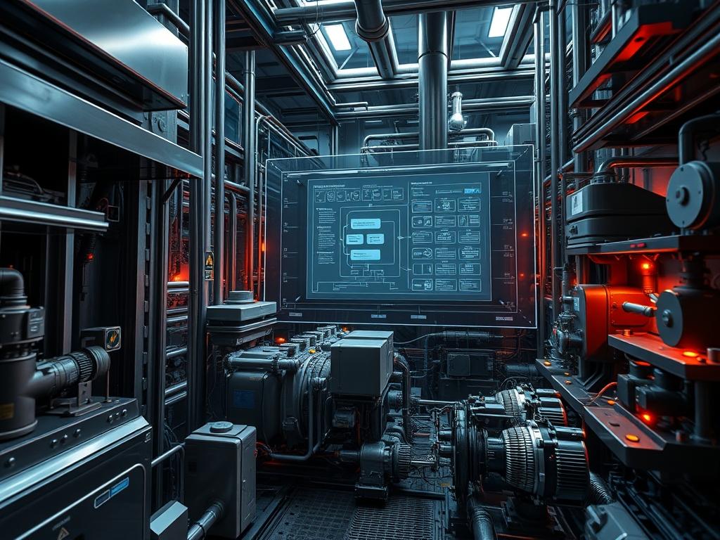
| Logic Interface | Port 502/TCP | Modbus/TCP | 6 | 8-Core CPU / 16GB RAM |
| Specific Gravity | 1.25 : 1.50 | ISO 2811 | 9 | Hydrometer/Sensors |
The Configuration Protocol (H3)
Environment Prerequisites:
Implementation requires strict adherence to IEEE 1547 for grid interconnection and NEC Article 706 for energy storage systems. All software control layers must run on a Real-Time Operating System (RTOS) or a hardened Linux kernel (e.g., Ubuntu with PREEMPT_RT patches). User permissions for the Field-Gateways must be restricted to the sysadmin group; with sudo access required for any modifications to the iptables or nftables firewall configurations.
Section A: Implementation Logic:
The engineering design relies on the idempotent nature of the redox reactions. In a VRFB; the same vanadium element is used in both the catholyte (V4+/V5+) and the anolyte (V2+/V3+). This design ensures that any ion migration across the Proton Exchange Membrane (PEM) is reversible. Unlike traditional batteries where signal-attenuation occurs due to solid-electrolyte interphase (SEI) layer growth; the VRFB maintains a consistent payload capacity over 20,000 cycles. The concurrency of the aqueous reactions is governed by the flow rate; which must be dynamically tuned to the electrical load to prevent concentration polarization.
Step-By-Step Execution (H3)
1. Initialize Control Logic Daemons
Execute systemctl enable vrfb-monitor.service followed by systemctl start vrfb-monitor.service.
System Note:
This action registers the monitoring service into the Linux init system; ensuring that the Open Circuit Voltage (OCV) data stream is persistent across hardware reboots of the Primary Logic Controller.
2. Calibrate Sensor I/O via Modbus
Use modbus-cli to write values to the holding registers at 0x0400 for pump velocity and 0x0405 for the stack temperature sensors.
System Note:
This step calibrates the ADC (Analog-to-Digital Converter) thresholds within the firmware. Proper calibration reduces the latency between a temperature spike and the automated trigger of the cooling loop.
3. Verify Electrolyte Specific Gravity
Utilize a fluke-multimeter or integrated optical sensors to measure the refractive index of the liquid in the Storage-Tanks.
System Note:
This physical verification ensures that the sulfuric acid concentration is within nominal bounds. If the specific gravity is off; the stack’s throughput will decrease due to increased internal resistance; mimicking the effects of packet-loss in a data network.
4. Execute Membrane Flux Test
Run the command ./membrane-test –flow-rate 20LPM –duration 600s on the Maintenance-Console.
System Note:
This stress test forces electrolyte through the stack at peak velocity. It checks the integrity of the seals and the PEM. Any pressure drop detected by the logic-controllers indicates a mechanical bottleneck or a leak in the encapsulation layer.
5. Finalize PID Controller Tuning
Adjust the Proportional-Integral-Derivative parameters in /etc/vrfb/control.conf to optimize pump speed relative to the State of Charge (SOC).
System Note:
By fine-tuning these parameters; you manage the thermal-inertia of the system. Excessive pump speed increases parasitic overhead; whereas insufficient speed leads to ion depletion at the membrane surface.
Section B: Dependency Fault-Lines:
The most critical failure point is the crossover of vanadium ions; which; while not damaging; causes a temporary imbalance in capacity. If the Primary-Stack detects a voltage imbalance exceeding 150mV; the system must initiate a “Rebalancing Cycle.” This involves transferring electrolyte between tanks to restore stoichiometry. Another bottleneck is the degradation of the carbon felt electrodes; which can lead to increased signal-attenuation in the voltage sense lines; resulting in false SOC readings.
The Troubleshooting Matrix (H3)
Section C: Logs & Debugging:
System logs are typically located at /var/log/vrfb/system.log. When diagnosing faults; look for specific error strings that correlate to physical sensor readouts.
1. ERROR_CODE_0x12 (LOW_FLOW): Check the Pump-Inverter for a tripped breaker. Verify the integrity of the Logic-Controller PWM signal using an oscilloscope or a high-end fluke-multimeter.
2. ERROR_CODE_0x45 (SOC_SKEW): This indicates the OCV cell reading does not match the integration of the current shunt data. Verify the Hall-Effect Sensor for interference.
3. LOG LINE: “Thermal runaway threshold approached”: Check the heat exchanger coolant levels. High thermal-inertia means that once the V5+ electrolyte reaches 45C; it will likely precipitate as V2O5 solids; which are difficult to re-dissolve.
Visual inspection of the Stack-Manifold is required if the logs show persistent pressure oscillations. These oscillations suggest air ingress in the suction line; which introduces oxygen as an unintended reactant; degrading the chemistry’s throughput.
Optimization & Hardening (H3)
Performance Tuning:
To maximize throughput; the electrolyte flow must be kept in a laminar regime within the tanks but transitioned to a turbulent regime within the stack channels to enhance mass transfer. Adjusting the pump’s VFD (Variable Frequency Drive) parameters to follow a non-linear curve relative to current density will reduce parasitic overhead. This optimization ensures that the concurrency of the ion transport matches the electrical demand of the DC-AC inverter.
Security Hardening:
The Logic-Controllers should be isolated on a separate VLAN. Use iptables to drop all incoming traffic on Port 502/TCP except from the authorized SCADA-Master IP address. Implement fail-safe physical logic; such as a mechanical pressure relief valve; to bypass software controls in the event of a kernel panic or a localized cyber-attack.
Scaling Logic:
Scaling a VRFB system is a matter of increasing tank volume (kWh capacity) or stack count (kW power). When expanding the stack array; use a parallel plumbing topology to ensure uniform pressure distribution. From a control perspective; assign each new stack a unique Modbus-ID and aggregate their data payloads into a single Master-Controller to maintain low-latency response times during grid transients.
The Admin Desk (H3)
FAQ 01: Can the electrolyte ever wear out?
No; the vanadium ions are not consumed. Longevity is limited only by the mechanical components like pumps and seals. Minor crossover is corrected by automated rebalancing; making the chemistry essentially immortal if the encapsulation remains intact.
FAQ 02: What is the impact of a total power loss?
Integrated logic-controllers will trigger a “Safe-State” shutdown. The pumps stop; and the electrolyte drains back into the tanks. Because there is no self-discharge in the tanks; the system maintains its SOC with nearly zero latency upon restart.
FAQ 03: Why use Vanadium over cheaper iron-flow?
Vanadium uses the same element in both half-cells. In iron-flow or zinc-bromine systems; cross-contamination leads to permanent capacity loss. Vanadium’s idempotent nature allows for indefinite cycling without the signal-attenuation found in hybrid flow chemistries.
FAQ 04: How do I handle V2O5 precipitation?
Precipitation occurs if the catholyte exceeds thermal limits. If detected; lower the SOC of the system and increase the flow rate to facilitate re-dissolution. Long-term prevention requires maintaining the thermal-inertia within the 10C-45C range via the HVAC controller.